Poor Man's UPS – Part 1
As a follow up to this post that I wrote a while back, one of things I have been thinking of doing is to have a reliable uninterrupted power supply. The setup is powered by a typical run-of-the-mill power bank which supports passthrough. However, these batteries typically rely on a mechanical relay which introduces a short break when the power switches from battery to mains supply. The unfortunate outcome is a hard power cycle of the RPi during power cuts that is pretty common in this part of the world! So, without further ado, let's look at our options.
A diode setup
Let's consider this simple circuit.
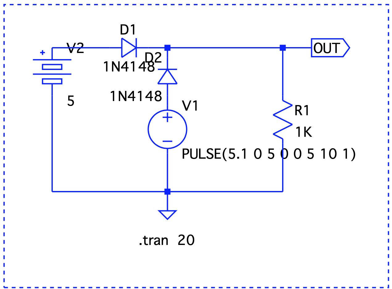
V1 simulates a pulse to show a sudden voltage drop to 0 (simulate a blackout). D1 and D2 are regular silicon diodes with a forward voltage of 0.7v. While the circuit protects the battery from getting damaged when mains is powering the RPi, the voltage drop brings the output voltage down significantly. We can replace these with germanium or Schottky diodes that have lower forward voltage drops. However, these come at the expense of higher reverse leakage currents and lower stability with temperature variations. Let's try something else.
A single MOSFET setup
A MOSFET can act as a switch with a lower forward voltage drop. Let's modify our original circuit and include a P-MOSFET.
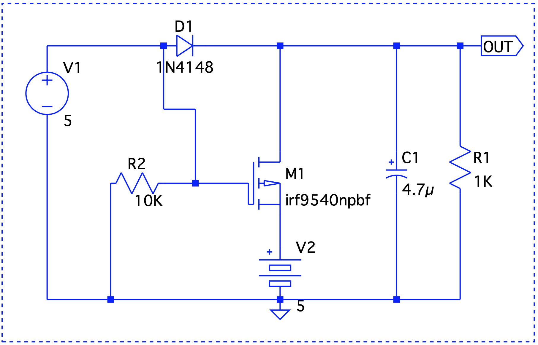
There are two issues here – First, our diode problem still remains and second, M1's drain to source path will try to charge the battery which may be undesirable. To understand why we need the diode, let's take a look at how the MOSFET operates. The P-channel of the MOSFET stops conducting when a positive gate voltage is applied. Now, if V1 were to turn off, M1 turns on and OUT now sources the battery. In the absence of the diode, the gate will be at the same potential as OUT which will turn it off!
Could we replace the diode D1 with another MOSFET ? Let's take a look at a simplified circuit that does that.

There's an important thing to point out – the MOSFETs are rotated, meaning, the source is connected to the point where drain should have been connected and vice versa. So, current always flows from drain to source. Or in other words, the semiconductor acts more as an off switch and simulates and ideal diode. But does it really work ? When V1 is on, there's a positive gate voltage at M2 and so current cannot flow into V2 and damage it. When V1 is 0, M2 is on and conducts in both directions.
We are approaching the ideal diode behavior but there's still a minor hiccup. When V2 > V1, the battery will start discharging even if V1 is on! The solution to that is to add another MOSFET to M2 but rotate it. Yet another issue in the previous circuit is that M1 is always on which might cause current to flow into it from V2 potentially damaging V1. The solution to that is to turn M1 on only when V1 is powering the circuit. This can easily be achieved with the help of a differential pair. The final circuit reflects these changes.
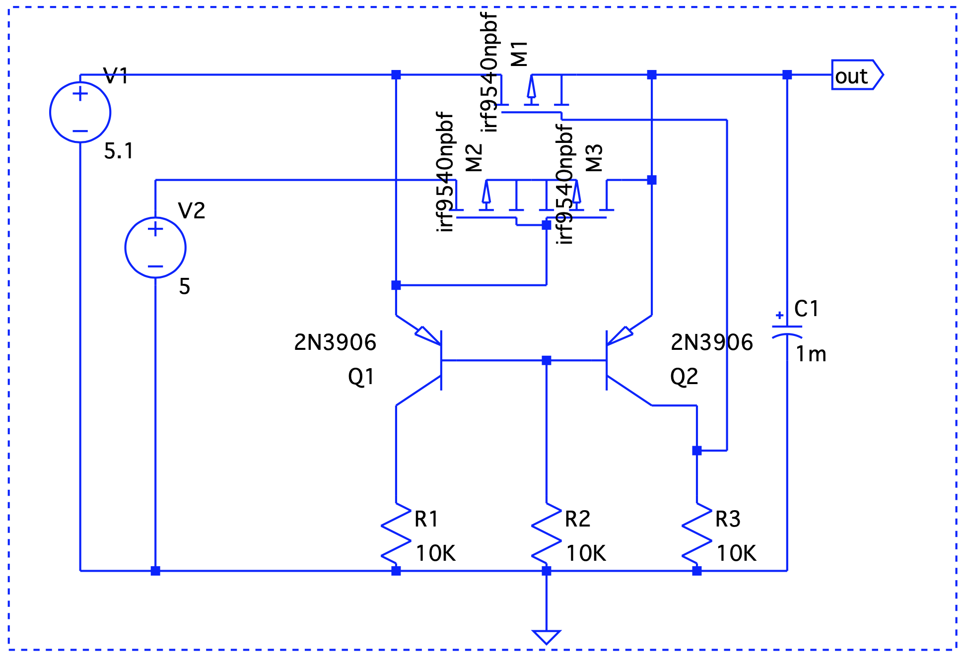
As mentioned above, M2 and M3 are the MOSFETS connected back-to-back and Q1 and Q2 form a differential pair. When V1 is active, Q1 conducts and M3 is off. This prevents current to flow out of V2. When V1 is off, Q2 conducts first which in turn will turn off M1. The battery now powers on the circuit. Let's take a look at a few use cases -
V1 = 5V > V2 = 4.8V
 Here, Vout is V1 – the forward voltage drop, so we are good.
V1 = 4.8V < V2 = 5V
 Even though V1 < V2, it still takes precedence.
V1 simulates a blackout – on/off/on.
 When V1 is on, it drives the output. V2 takes over at t=2 and until t=6.
In the next part, we will decide on taking this circuit out on a drive in the real world and/or investigate solutions that already do this job such as the CAT6500 (now obsolete!).