th.oughts

diy

Problem Statement

I wanted a cheap backup VPN tunnel to reinforce my main tunnel in case things go wrong. The backup tunnel is on standby and is utilized only when I need an alternate path to investigate why my main network is down or isn't functioning when I am physically away from my systems.

Challenges

CG-NAT has ruined cellular network based data plans. Cellular networks have kept their eccentric design choices throughout their evolution even though they have leveraged a lot from regular internet based data networks. CG-NAT is one of those inconvenient design choices that has stayed on. To summarize, a lot of the cheap MVNO data plans operate like a NATed LAN and incoming connections aren't really possible because you do not get gifted with a public IP. Setting up a VPN tunnel using one of these data networks becomes a bendy road to success.

Design choices

Using a cheap data plan is quite appealing because I would ideally want the cost to be as low as possible without sacrificing much on the minimum reliability that you would expect from a backup network.

Owing to the design restrictions mentioned above, you cannot simply dial in to your backup VPN endpoint. The connection has to be initiated in the opposite direction. This post details how I achieved an usable setup without sacrificing too much on cost or reliability.

Network topology

Network Topology

Click here for a somewhat legible image.

Main LAN (1)

The main network gated by a OpenBSD based firewall and gateway.

BMC (2)

The base management controller to control the gateway.

CRS 326 (3)

This is the backup gateway using a Mikrotik CRS326. It's probably overkill for what I am trying to achieve. It provides three different functions in our setup:

Backup firewall/gateway

Creates another smaller LAN composed of BMCs for systems that provide services. This LAN is also accessible from the main LAN. This is simple using masquerade rules.

On Mikrotik:

chain=srcnat action=masquerade out-interface=<backuplanbridge> log=yes log-prefix="BackupLANBridge>"

Note that, for this to work, one of the interfaces of backup gateway's bridged network should be a dhcp client on the main LAN.

The backup firewall is connected to the internet via the LM1200 (4).

Scheduler

We also use the scheduler function of the Mikrotik box. It checks a cookie at regular intervals in case user has requested VPN to be on. While you have a always-on tunnel, I would like to minimize data usage on the data only SIM (the backup network).

A simple script to check a variable on remote web server(RouterOS):

# Check if user has enabled cookie
	:local result [/tool fetch url="<path to remote web server>/radar.txt" mode=https as-value output=user ]
	:delay 5
        :local dat ($result->"data")
        :log info ("Wireguard, Cookie is:$dat")

# check if user wants to run tunnel
       :if ( [: pick $dat 0 1]  != "0") do={
            :local status [/interface get <wireguard interface> disabled];
             :if ($status=true) do={
                  :log info "Trying to enable wireguard interface";
                  /interface/wireguard/enable <wireguard interface>;
                  :delay 5;
            } else={
                         :log info "Wireguard interface already enabled";
            }
             # For debugging
            /ping count=5 10.8.0.1; 
        } else={
                     :log info "Trying to disable wireguard interface";
                     /interface/wireguard/disable <wireguard interface>;       
      }

To set this to run every 5 minutes:

add disabled=no interval=5m name=<myscript>

Wireguard endpoint

This is the configured interface we have referred above in the script.

LM1200 (4)

This is most convenient device I could find for my needs. It takes in a data sim and gives you a bridged interface.

CG-NAT (5)

The cellular network.

I use a publicly accessible S3 bucket for my cookie. All it needs is writing a 0 or 1 to a text file.

Wireguard Server (7)

This is another critical piece of the setup. It serves as a bridge between the roaming endpoint and the local site. Besides the necessary firewall rules, some masquerade and postrouting rules are required:

iptables -t nat -I POSTROUTING -o eth0 -j MASQUERADE
iptables -t mangle -A POSTROUTING -p tcp --tcp-flags SYN,RST SYN -o wg0 -j TCPMSS --set-mss 1280

The mangle is essential since we are accessing the tunnel indirectly via another system. Note that instead of setting a —set-mss value explicitly, you can just use —clamp-mss-to-pmtu that automatically sets an appropriate value.

Roaming system configuration

Before we get to our script that makes life a bit easier, here's the typical workflow:

  1. User detects that the main network is down and primary VPN does not work.
  2. User sets cookie in the S3 bucket to 1.
  3. User waits for the remote backup system to initiate a wireguard tunnel.
  4. Once done, user uses a ssh tunnel or a wireguard tunnel to the wireguard server.

Here's a script that does something similar.
#networking #diy

Discuss...

In Part 1, we had a quick introduction to tapes and tape drives and why you would choose one for your backups. In this part, we talk about actually using tapes to create a backup strategy using simple scripting.

Of course, there are plenty of readily available tools that might suit your needs. Writing your own does have a few advantages though: first, it keeps it simple, highly customized and second, when things go wrong, you would probably have a better idea of why the damn thing isn't working!

A look at tape's workings

If this is your first time dealing with tapes(as it was for me), there's a few prerequisites.

Tools

Tape operations are carried out via the mt tool. Data is written with tar. Both of these are probably already installed on your system.

Writing data to tapes

Do you remember the good old days of cassette players ? Tapes are similar. A magnetic head reads and writes data from a magnetic ribbon spooled in an enclosure. With that in mind, there are a few operations that you would do frequently:

  1. rewind: rewinds(of course!) the tape and points the tape head to the beginning of the magnetic ribbon. Example command: mt -f /dev/nst0 rewind

  2. forward: Move forward count files. Every time data is written, a marker is set at the end. Let's say, you write some data to the beginning of the tape: tar cvf /dev/nst0 backupdir Rewind the tape as above. Now, you want to move forward one marker: mt -f /dev/nst0 fsf 1

  3. erase: That's a really slow process and could take hours (if not days) for larger tapes. However, you can also do a short erase: mt -f /dev/nst0 erase 0.

Tar and incremental backups

tar has a handy feature that lets you do incremental backups and the workings are really simple. Let's look at an example:

  1. tar -C /home —listed-incremental=diff.snar -clpMvf /dev/nst0 data This is what we call a Level 0 backup. diff.snar is special – it contains a log of all the files that were added to the archive.

  2. Next, lets's say you add file.txt to folder data and run the above command again. The only file that would be added to the archive is file.txt. Moreover, diff.snar would also be overwritten with the only one entry that was just added to the archive. This would be a Level 1 archive.

Obviously, if you would want to have a record of all the backups, you wouldn't want to overwrite diff.snar but have rather something like this:

  • diff0.snar: level0 backup
  • diff1.snar: level1 backup and so on...

Backup Strategy

With all this quick preliminary information, we can try a incremental backup strategy as follows:

  1. Maintain two sets of full backup tapes and two sets of incremental backup tapes.
  2. Create a full backup the start of every cycle: could be a month, bimonthly, quarterly or whatever you prefer.
  3. Until the beginning of next cycle, perform incremental backups.
  4. At any point of time, you should always have a backup set that has a full backup of the last cycle as well as incremental backup tape(s) of the last cycle.

Tape utility script illustrates the idea. To perform a full backup, you would run something like:

tapeutility.sh -d /dev/nst0 -F -p /etc/tapeutility/folders.txt where “-F” does a full backup of folders listed in “folders.txt”.

For the next run, to create an incremental backup, you would run: tapeutility.sh -d /dev/nst0 -I -p /etc/tapeutility/folders.txt where “-I” does an incremental backup.

Please take a look at the script for how the metadata file is determined for incremental backup and other features available for basic tape maintenance.

Wrap-up

I presented a simple way to use tapes for backups. Using a combination of full and incremental backups, and maintaining two sets of tapes, we have reliable backup of data that you could combine with a RAID style setup for long term reliable data storage.

#backups #bash #diy

Discuss...

As a follow up to this post that I wrote a while back, one of things I have been thinking of doing is to have a reliable uninterrupted power supply. The setup is powered by a typical run-of-the-mill power bank which supports passthrough. However, these batteries typically rely on a mechanical relay which introduces a short break when the power switches from battery to mains supply. The unfortunate outcome is a hard power cycle of the RPi during power cuts that is pretty common in this part of the world! So, without further ado, let's look at our options.

A diode setup

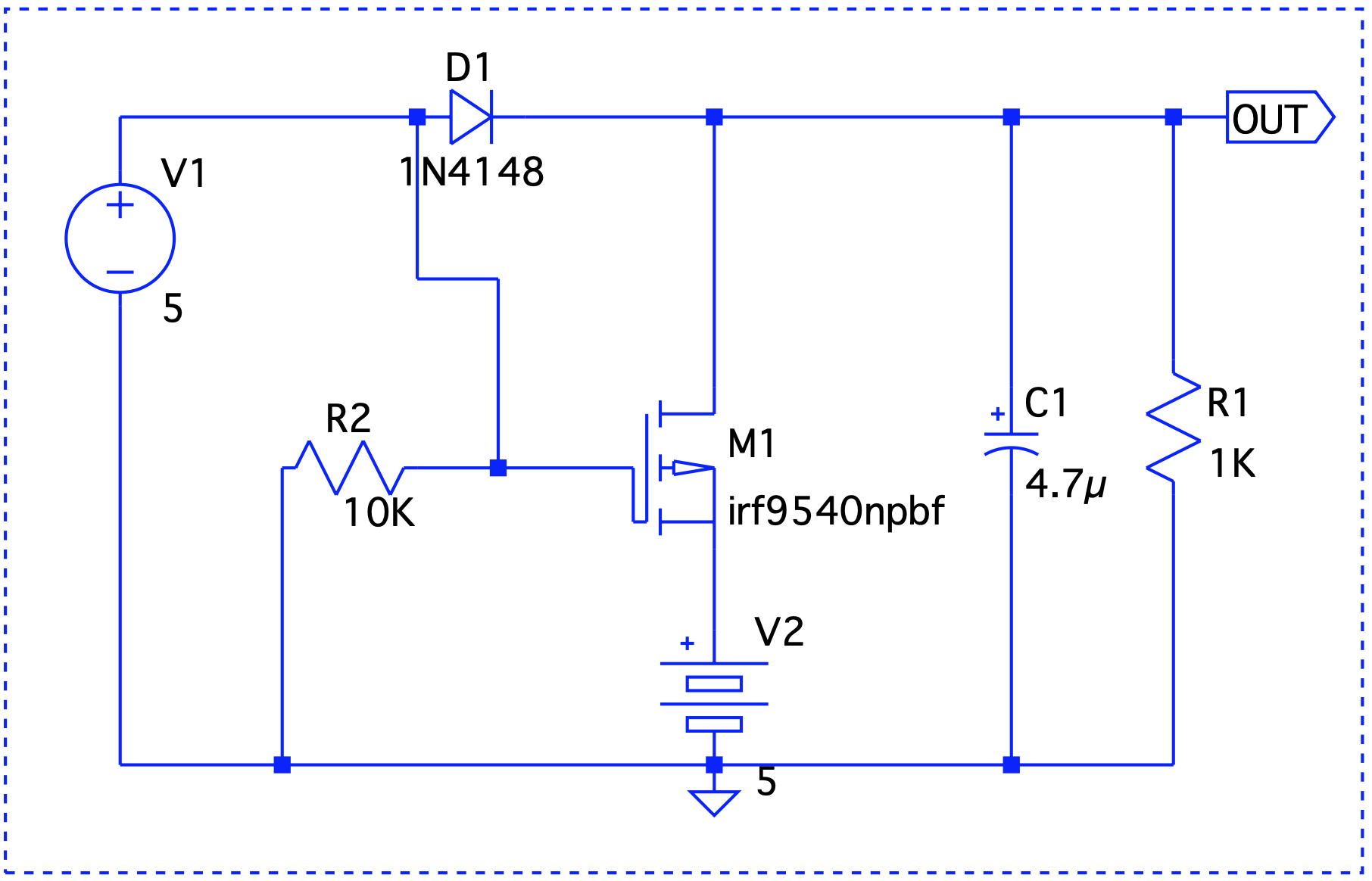
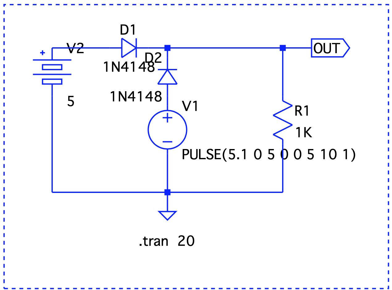
Let's consider this simple circuit. Diode as a forward switch

V1 simulates a pulse to show a sudden voltage drop to 0 (simulate a blackout). D1 and D2 are regular silicon diodes with a forward voltage of 0.7v. While the circuit protects the battery from getting damaged when mains is powering the RPi, the voltage drop brings the output voltage down significantly. We can replace these with germanium or Schottky diodes that have lower forward voltage drops. However, these come at the expense of higher reverse leakage currents and lower stability with temperature variations. Let's try something else.

A single MOSFET setup

A MOSFET can act as a switch with a lower forward voltage drop. Let's modify our original circuit and include a P-MOSFET. MOSFET as a switch

There are two issues here – First, our diode problem still remains and second, M1's drain to source path will try to charge the battery which may be undesirable. To understand why we need the diode, let's take a look at how the MOSFET operates. The P-channel of the MOSFET stops conducting when a positive gate voltage is applied. Now, if V1 were to turn off, M1 turns on and OUT now sources the battery. In the absence of the diode, the gate will be at the same potential as OUT which will turn it off!

Could we replace the diode D1 with another MOSFET ? Let's take a look at a simplified circuit that does that.

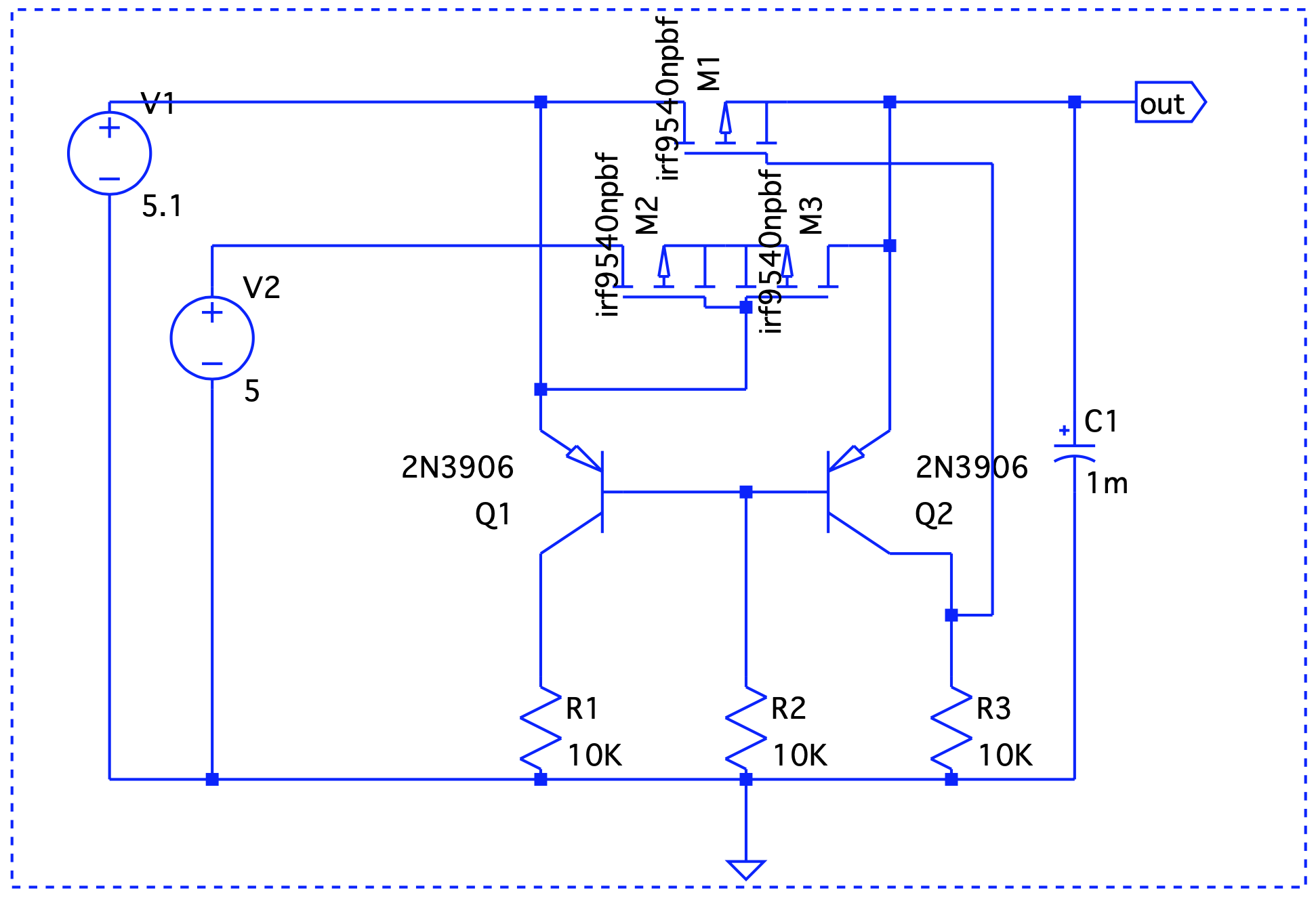
Rotated MOSFET setup

There's an important thing to point out – the MOSFETs are rotated, meaning, the source is connected to the point where drain should have been connected and vice versa. So, current always flows from drain to source. Or in other words, the semiconductor acts more as an off switch and simulates and ideal diode. But does it really work ? When V1 is on, there's a positive gate voltage at M2 and so current cannot flow into V2 and damage it. When V1 is 0, M2 is on and conducts in both directions.

We are approaching the ideal diode behavior but there's still a minor hiccup. When V2 > V1, the battery will start discharging even if V1 is on! The solution to that is to add another MOSFET to M2 but rotate it. Yet another issue in the previous circuit is that M1 is always on which might cause current to flow into it from V2 potentially damaging V1. The solution to that is to turn M1 on only when V1 is powering the circuit. This can easily be achieved with the help of a differential pair. The final circuit reflects these changes.

Final Circuit

As mentioned above, M2 and M3 are the MOSFETS connected back-to-back and Q1 and Q2 form a differential pair. When V1 is active, Q1 conducts and M3 is off. This prevents current to flow out of V2. When V1 is off, Q2 conducts first which in turn will turn off M1. The battery now powers on the circuit. Let's take a look at a few use cases -

  1. V1 = 5V > V2 = 4.8V Graph1 Here, Vout is V1 – the forward voltage drop, so we are good.

  2. V1 = 4.8V < V2 = 5V Graph2 Even though V1 < V2, it still takes precedence.

  3. V1 simulates a blackout – on/off/on. Graph3 When V1 is on, it drives the output. V2 takes over at t=2 and until t=6.

In the next part, we will decide on taking this circuit out on a drive in the real world and/or investigate solutions that already do this job such as the CAT6500 (now obsolete!).

#tech #diy #electronics #mosfets

Discuss...

A while back, my rusty Sans Digital TowerRAID gave up. Honestly, it had not been a very expensive investment, presumably, at the cost of reliability. Nevertheless, I got a few good years out of it. From the looks of it, it looked like the power supply failed and although, I could have replaced the power supply board, I decided to venture out for future proofing my storage requirements.

Upgrading from a 4 slot JBOD enclosure to 8 disks enclosure

Pretty much everything out there comes at a price of greater than $500 for a 8 slot JBOD. Most of them don't have decent reviews and the ones that do are usually more expensive. That led me to the other option.

DIY

I wanted to explore this option before I splurged on a brand name enclosure. Luckily, there were many helpful resources available that led me to believe this is indeed a possibility. Below, you will find a BOM of what went into my DIY JBOD. The heart of the device is a RAID expander. Ofcourse, you also need to invest in a decent enclosure that houses everything.

RAID Expander ~$60

The item we are looking at is a discontinued Intel RES2SV240 that you can still find on Ebay and some other stores. This was more than enough for my needs – It supports SAS-2. it has 24 ports- 4 ports/1 socket connects to the cable, that in turn connects to the SAS initiator. The rest can be connected to disks – so, you can plug in 20 disks theoretically.

Power Board ~$70

This one's optional in my opinion but it does make the whole setup a little more polished. The one that I used is a SuperMicro CSE-PTJBOD-CB2, again, pretty easily available on Ebay. What this does is let you use the enclosure switch to control power to the system. This would not have been possible otherwise, without a motherboard.

Mini SAS SFF-8088 to SFF-8087 Adapter ~ $25

This will be our portal to the outside world. The SFF-8088 cable (that I already have) will connect the expander to the initiator on the server. The one that I got(CableDeconn) conveniently fits into a full height PCI slot on the enclosure.

SFF-8087 to 4 SATA ~$20

This goes from the RAID expander to the backplane in the enclosure that we will use. Since I plan to use 8 disks, I got two of the cables.

SFF-8087 to SFF-8087 cable ~$8

This cable connects the expander on one end and the SFF-8088 to SFF-8087 adapter on the other end.

Power supply ~$50

Nothing special here, I used a 430W 80+ ATX supply but that's more than what you would need.

Enclosure ~$160

This was the most expensive buy for the project but it's worth it. I decided on a SilverStone CS380B which doesn't have stellar reviews, to be honest, most complained about unsatisfactory ventilation but I was sure I would be fine because I wouldn't install a motherboard in it.

Fitting everything together

The enclosure already has a backplane for the disks. The RAID expander card as well as the SFF-8087 to 8088 adapter both went into a slot on the enclosure where a full height card would usually go. I had to drill some holes so that the power board could stay in place.

Here's a pic of the innards after everything has been fixed in place: Enclosure

Total cost and troubleshooting

Total cost comes out to be ~$400 which is still a good price for a system that can house more than 8 disks (The Silverstone has internal bays for a few more).

There's nothing here that could go wrong. Everything's pretty much plug and play. The only thing worth noting is that the expander card has been discontinued and there's probably not a lot of them out there. You might end up getting a dead card. If things don't work out as expected, just blame it on the card and get a replacement! :)

My setup has been going strong for a few months now. I am glad I went this route!

References: https://www.servethehome.com/sas-expanders-diy-cheap-low-cost-jbod-enclosures-raid/ https://forums.servethehome.com/index.php?threads/diy-jbod-chassis-this-all-i-need.23903/

#tech #diy #jbod

Discuss...

My Dad had a specific set of requirements from a security camera he wanted for our home back in India. When I researched between options, on whether to buy one or to build something, I stumbled upon many builds based on the Raspberry Pi. Most successful builds run Motion on top of a RPi board, or maybe, even Motioneye for a friendlier UI. This post summarizes the issues that I/you are likely to face and what I did about them.

Underwhelming hardware

I used a RPi 3 B board that has a 1.2 Ghz quadcore ARM processor. For processing a video stream and running the motion detection daemon, it's not really very capable and you would end up with stuck/unusable frames on your stream. One of the things that makes a huge difference is the incoming stream frame rate and resolution. I got the best results with sliding down the incoming frame rate to as low as 10 on the camera that I am using.

B vs B+

The B+'s advantage is more on the I/O side and it really doesn't make much of a difference with processing power when it comes to the video stream. On the other hand, the B is more battery friendly which was a major requirement in my setup owing to the frequent power-cuts associated with Indian summers. Overclocking, too, isn't worth it if you consider the battery drain (as high as 20% faster) compared to any noticeable performance gain.

Backup power

As mentioned above, this was an important requirement. I used a 20000 mAH battery that has passthrough. On the downside, when passthrough triggers, there's a momentary disconnect in power which restarts the camera and the RPi which is undesirable but the small downtime is acceptable.

Network

One of the requirements was failover to a backup network but jumping back to the main network once it's back up. A reverse tunnel to a public IP takes care of ssh and http access and could be easily scripted as well. HTTPS is achieved by setting up a nginx reverse proxy on the public facing system and integrating with letsencrypt.

Motion detection

False positives is a major challenge and I could get a good compromise with a mix of a few things: – Setting up a manual mask. This is easy to do with the motioneye http interface. – Using a despeckle filter. Take a look at this article for a nice write up by the author. After experimenting with several combinations, EedDl gave the best results (which also happens to be the recommended starting poin). – Experimenting with thresholds. I used the threshold_maximum parameter to minimize the maximum pixel change. A script changes the threshold value based on input from a LDR similar to this setup.

Usability

The system is easy to use/configure with the Motioneye http interface but to make it a little bit more interesting, I used some NFC tags to enable/disable motion detection. This can be easily done with Tasker along with the NFC plugin for it. This script takes care of syncing up the config file with the current state of motion detection.

#thoughts #tech #diy #rpi #bash

Discuss...